Correct installation will make or break (literally) a pump rebuild.
These early pumps are much maligned and misunderstood. It would seem easier to install a new C / 912 or a electric fuel pump than go through the work of correctly installing the A pump.
Keep in mind the fuel delivery pressure is determined by the diaphragm spring---not the push-rod stroke!
The stroke is predetermined by the distributor cam lobe. We just want to use part of it to cock or load the spring.
All important here is the use of gaskets as shims.
Installation
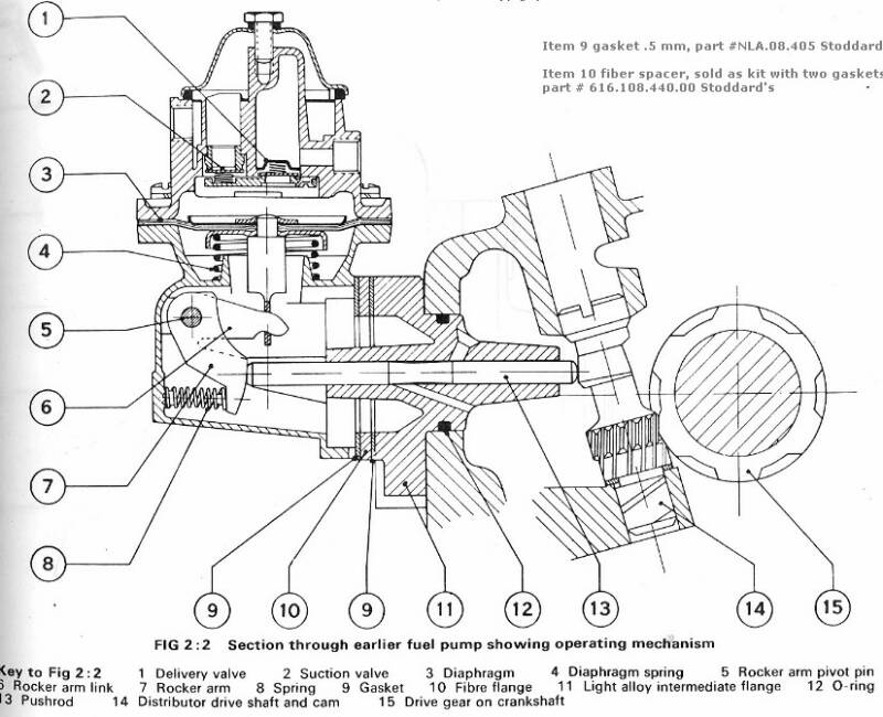
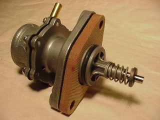
As described above there is a 5 mm Min / Max range for the stroke. The actualpush rod stroke is 4 mm. As seen in Fig 1:7, item 9, we need a minimum of two gaskets installed (gaskets are approximate .5 mm) that leaves 3 mm working stroke. You can install the flange as above without the VW tool, but with nuts and washers for partial compression. Take measurements from flange face (not push-rod boss) to rod end as engine is rotated. The fuel pump is driven off of a cam on the distributor drive shaft. You need to rotate the crankshaft two rotations for full stroke. Then make allowances for gasket compression. This measurement should never be more than 33 mm! You will probably be less than 33 mm, and that's good. This would be our allowance for gasket compression. Keep in mind as gaskets are compressed, effective working stroke will increase.
Make it easy, use my three gasket / shim set. When installed and compressed will give a working stroke of 2 mm to 2.5mm. From the previous description of operation on the Home Page, we know under normal operating conditions the diaphragm needs only some .02" or .5 mm of working stroke. Given our pump is mechanically sound, we have ample working stroke.
Here is the 356 A Service Manual description of adjusting the stroke of fuel pump. " Install intermediate flange, gasket, fiber flange spacer, gasket, actuating rod, or push-rod (round end toward distributor cam) and VW tool # 328A. Tighten to compress gaskets.
Rotate engine and measure stroke. It should move within the range of 29 MM and 34 MM as measured from flange face to rod end. Stroke can be adjusted by fitting appropriate number of gaskets to flange. Do not fit less gaskets than required, as this will have a detrimental effect on the diaphragm and the drive mechanism."
Now that we know how many gaskets are needed the pump can be installed.
First, be sure to fill the lower housing with fresh grease. Approximate 75%-80% full, so that there is room for the diaphragm to move down..
At operating temperature the grease assumes a liquid condition, thus lubricating all moving parts. It is further helped by engine oil which is fed into the housing from a hole in the intermediate flange.
This may seem confusing, but take your time to make measurements and visualize what is taking place.
More gaskets are better, to a point (less stress on drive mechanism), but we do not want to run out of working stroke.
Stroke Adjustment
These pages are still under construction and revision, any coments welcome
Thanks for looking...... Doug
Notes: DVG Fuel Pump
Staked pins.
Early A pumps as well as Pre A pumps had the rocker arm pin staked to the housing. This pin could work loose and fall out, leaving both the pump and car dead. In disassembling pumps I have found that it does not take much effort to push out these pins.
Most pumps marked DVG have a large boss for the rocker pin. This area is were the pin was staked. Later pumps marked just, Made in W Germany have a smaller boss. By this time DVG stopped staking pins and started using a longer pin with retaining clips to keep it in place. See Fig 1:5 for differences.
Replacement pins.
I machine these in my shop. They are the longer ones with retaining clips to keep them in place.
Valve discs & seats.
Valve seats;
Early pumps had machined brass insert suction valve seat ( hard seat). Later pumps (after 58' ?) suction valve seat is now cast into body (soft seat).
Valve disc;
It seems the brass insert valve seat could tolerate the hard Phenolic / fiber valve disc ( no soft face) this is a carry over from the early VW 25HP, 36HP & 356 Pre-A fuel pumps.
The valve disc with soft face appears when the 356 DVG fuel pump production changed to cast-in suction valve seat (soft seat).
Rocker arm wear. When you remove your fuel pump for repair or inspection, make note of the wear marks made by the push rod on rocker arm face. The height of the marks indicates actual push rod stroke. The position on the face, high or low, gives a quick visual indication if you have the right spacing or number of gaskets.
As seen in Fig 1:6 , the rocker arm on the right has deep wear marks high on the face. This indicates spacing too close, which is the same as not enough gaskets. Ideally the wear mark should be lower, it would start 4-5 mm below top of face.
Fuel Pump pressure and flow
The DVG pump in good repair and in normal operation can maintain 7" Hg vacuum at inlet and 2.4 PSI at outlet. 7" Hg converted to PSI = 3.4 PSI plus 2.4 PSI outlet, gives a delta P of 5.8 PSI. These are good numbers for for a diaphragm that moves only some .5 mm.
At 60 MPH and 25 MPG requires only 2.4 GPH.
As I noted earlier, when rebuilt properly. This robust self regulating surge chamber pump and can deliver copious quantities of fuel at a constant 2.0-2.4 PSI.
I put this information here to counter the creeping misunderstanding out there that the 356 cars would benefit with installation of an electric fuel pump.
Early ( and some vintage ) racers knew this and relied on these pumps.
This information applies to the large DVG - Rokal fuel pump used in:
Porsche 356 pre-A & A/B cars.
VW 25HP & 36 HP motors.
A Gasoline powered engine at full power: 300 HP needs 24.5 GPH, 200 HP needs 17 GPH, 100 HP needs 8.5 GPH
Note: Installation information provided below assumes fuel pump has been rebuilt to or near factory new condition. Fuel pump mounting flange face must be true (flat), otherwise installation measurements are meaningless.
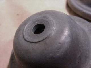
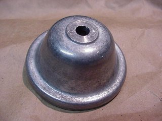
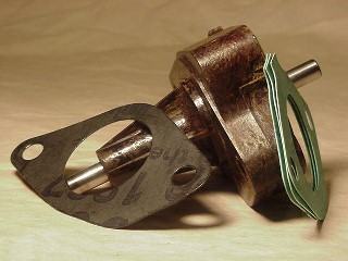
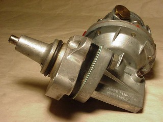
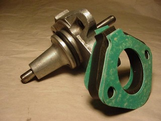
When the sealing flange at top of cone is flush and smooth, it does not take much to seal it...
Flat & true, no problem sealing.
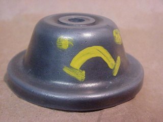
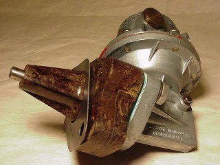
Typically worn & deformed. As is, this will be a real problem to seal. Even with a new washer, it will leak.
Why is Little Cone so Sad?
Pix of intermediate flange's used with the DVG fuel pump.
Upper pix shows very early phenoelic/fiber insulating flange with correct positioning of gaskets.
Note: Flange is sealed to motor case with gasket. I use this style flange on my 56 coupe. It provides excellent insulation from motor heat. Its weakness; deformation and stripped threads from over tightening.
They are hard to find in serviceable shape.
Lower pix shows later alloy flange, it's insulating spacer and correct positioning of gaskets.
Note: Flange is now sealed to motor case with O'ring.
Several used alloy flange & rod assembles available, ask. Also new spacers and gaskets in stock.
If you are converting back to original (early style) DVG pump from an installed (late style) APG pump on your 356 A/B car. You will need the parts illustrated above (intermediate flange, rod, spacer, gaskets and O' ring) along with the DVG pump to complete the conversion.
Converting from the late style APG fuel pump
356 A/B early Fuel Pump
356 A/B early Fuel Pump
Grease Note:
The 'A' service manual recommends filling the lower housings with special grease " anti-freeze ".
Sounds strange, but probably just the technical translation from period (1955) original German.
I use chassis cartridge grease. In my experience the moly ( molybdenum) or dark base grease holds up better at temperature than the lithium or light base greases.
Note: Top bolt When tightening down cone top. Snug is good. If still leaking, ' STOP 'and address problem ( gaskets, mating areas , compressed cone that bottoms-out on thread boss ).Over tightening leads to top deformation and stripped threads.
My fuel pump bench rebuilds incorporate
American made parts including:
Premium grade nylon inserted nitrile diaphragm fabric suitable for all aromatic fuels
Proprietary;
PTFE (Teflon) valve discs
Stainless steel valve springs
Diaphragm spring
Fuel screen / filter w/ 150 micron rating
Gaskets and red vulcanized fibre compressed washers
Impervious to any fuel chemicals & last a life time with virtually no valve disc or valve seat wear, while delivering fuel at consistent 2.0 to 2.4 PSI...
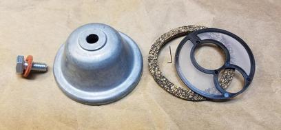
If your fuel pump top is a problem leaker replace with my Cone Top Kit. Includes OEM New, (NOS - German) Top, New top bolt, Top Bolt Washer, Fuel Screen and Screen Gasket. ( everything in below picture )